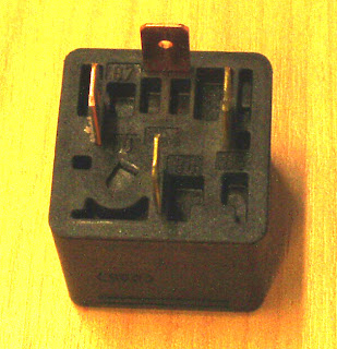
5 pin relay
86 positve side of control with 85 as the negative. 30 is battery supply for the switched circuit and 87a is normally closed switch circuit,87 is the other switch
in the above picture the black is the negative pin 85,the bottom two pins are the positive powewrd 86 and 30,
top red clip is the switch when closed with 87a in the middle and 87 pin to the light bulb with the green clip
Circuit Off Circuit On
86 0 V 86: 12.09 V
85 V 85 0 V
30 12.09mV 30 12.8 V
87a 12.09V 87a 0 V
87 0 V 87 12.8V
first two pics show the relay used in class with an assigned switch to simulate headlights turning on and off.
last picture is of a four pin relay
..works similar to the five pin except the 5 pin has another switch circuit
(http://www.reuk.co.uk/Automotive-Relays.htm)
testing the relays
Resistance of circuits...86 to 85 88.2 Ω
30 to 87a 0.2 Ω
30 to 87 0.2 Ω
Control circuit that switches the points: __85__,86
Switched points that carry the higher amps: _30_, 87(87a)
If 12volts are used, the amperage would be: 12 V / 88.2 ohms = 0.136 A
in the drawing below the relay control is the switch for the light bulb.in this case it is off.
 following it one of a two light bulb circuit, as the points are switched one of the two bulbs will be on,in this case the high beam because the point is closed


No comments:
Post a Comment